Wednesday, February 27, 2013

Handwriting Recognition Using MATLAB

Alright Now, I have been a little Preoccupied with studies, but as usual i found out time for some fiddling with image processing. I chose MATLAB because of its simplicity. Sure, there are more powerful tools available out there, but for the basic understanding i think i did a pretty good job with "Handwriting Recognition using MATLAB"

Check Out This Video To See How It Works :


Well, I will be updating this post in some days, this code is up for sale .

Monday, August 20, 2012

WIRELESS POWER TRANSFER


Wireless Energy Transfer or Wireless Power is the transmission of electrical energy from a power source to an electrical load without interconnecting man made conductors.  Wireless transmission is useful in cases where interconnecting wires are inconvenient, hazardous, or impossible.  The problem of wireless power transmission differs from that of wireless telecommunications, such as radio.  In the latter, the proportion of energy received becomes critical only if it is too low for the signal to be distinguished from the background noiseWith wireless power, efficiency is the more significant parameter.  A large part of the energy sent out by the generating plant must arrive at the receiver or receivers to make the system economical.
- Wikipedia.

I hate to go into the theory because i am kind of a  practical person..who scores much better in practicals rather than writing mindless theory papers judged by some bookworms who wouldn't try to question any standards, as if they even qualified to be labelled as standards..Indian education system boss..it can make an elephant chirp and a bird roar..okay so lets cut the crap and start making a wireless power transfer system.


A bit of theory just to brush up your basics :

So, basically wireless power transfer is nothing more than a transformer without a core..without a core so without a channel..without a channel so less energy concentration and more loss..more loss, well.. less output..less output ...useless.


Just So You Were Wondering, This Is A Transformer


And This Is A Transformer From  Cybertron

So Nikola Tesla, a great scientist told the world that in resonance the system is optimized and maximum efficiency is achieved at near distances..near he said, and still managed to light a bulb almost a mile away!!

Now i ain't Tesla, so near for me is actually near. Well, today we will try to light white leds at a distance of 8-10 cms away from the transmitter.


Prerequisites :

1. 4.5V / 5V Batteries.
2. Capacitors  (Polypropylene)
                    a. C1 - 1nF
                    b. C3,C5 - 4,7 nf
                    c. C4,C6 - 220nf
3. 19 SWG Enameled Wire.
4. White Leds, Red Leds.
5. Bread Board.
6. Connecting Wires.
7. Electric Tape.
8. Digital Multimeter.
9. Diode D1 - BAT46 (i used this), 1N4148.
10. Transistor T1 - BD137, BD139 (i used this), BD639.
11. Resistor R1 - 5.1k 

Schematics:


Transmitter, The Three Ends Are Left Out For The Coils

                            Receiver, Connect The Coils To The Ends Shown                             

Coils:
So Now You Get A Good Idea On How Many Turns And What Thickness

No. of Turns : 4 on each (2 + 2) 


Check Out This Video : Wireless Power Transfer Demonstration

 
Well, That's It. There You Have A Working Prototype of Wireless Power Transfer System Using Inductive Coupling. I will Try To Upload My Own Detailed Video Where I Make Everything From Scratch..And Tackle The Difficulties I face In The Way..Till Then Ciao!!

Friday, August 10, 2012

AUGMENTED REALITY

Augmented reality is considered an extension of virtual reality. Virtual reality (VR) is a virtual space in which players immerse themselves into that space and exceed the bounds of physical reality. 
Pranav Mistry's Sixth Sense Technology

Now that you know what we are talking about let's start making something. Today i am going to show you how you can embed a video to a marker more like how Pranav Mistry does while watching a video of Obama's speech in MIT on a newspaper. See his Ted Talks demonstration of SixthSense Technology.


Prerequisites:

1. Adobe Flash Builder 4.6 
Download Here : http://www.adobe.com/products/flash-builder.html

2. Papervision3D 2.0.883  
Download Here :http://code.google.com/p/papervision3d/downloads/list

3. FLARManager v06      
 Download Here : http://words.transmote.com/wp/flarmanager/

4. Webcam
5. Pocket Projector (Optional)
6. Windows or Mac OS

Step 1:

Download all the necessary software mentioned above and create a new folder either in C drive or D drive. Name it as "Actionscript". Now in this folder add folders "org" and "com" which you will find in FLARManager v06 folder. Also add the folders "papervision3D" and "ascollada" (which you will find in Papervision3D 2.0.883 folder) in the "org" folder under "Actionscript" directory.


Step 2:

Open Adobe Flash Builder 4.6 

File > New > Actionscript Project 
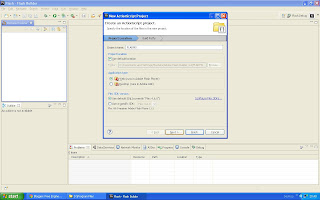

Figure 1


Project name : FLARMS ( You can Put any name you like )

Click on "Next" leaving all other settings as shown in Figure1.
Now click on "Source path" tab just adjacent to "Library path" then Add Folder and select your global "Actionscript" Directory that we just set up in Step 1. See Figure 2
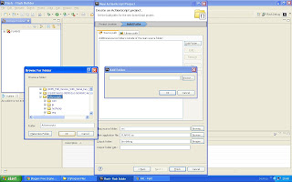
Figure 2

After loading the Actionscript directory click on finish and the project should load all the files in the package explorer window and the FLARMS.as file should show up. See Figure 3
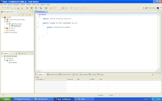
Figure 3

Step 3:

Use the Code From The Source Code File Provided In The End.

Now Import The FLARManager v06 project into your package explorer


File > Import Flash Builder Project > Project Folder > Browse > FLARManager v06 > Finish

FLARManager v06 > resources > flar

Copy "FLARCameraParams.dat" and "flarConfig.xml" file and paste it in "src" of FLARMS.

Download any m4v video and paste it into "src" of FLARMS.
( This is the video that you would watch on the marker )

Now open the "flarConfig.xml" in "src" of FLARMS folder and edit it to match the following code:

<!-- this file specifies configurations for FLARManager. -->
<!-- to use this file to initialize FLARManager, pass its path into FLARManager.initFromFile(). -->
<!-- note that all relative paths listed here must be relative to the .swf location; absolute paths may also be used. -->

<flar_config>
<!-- source settings -->
<flarSourceSettings
sourceWidth="320"
sourceHeight="240"
displayWidth="640"
displayHeight="480"
framerate="30"
downsampleRatio="1" />

<!-- miscellaneous FLARManager settings -->

<flarManagerSettings
mirrorDisplay="true"
smoothing="3">
<smoother className="FLARMatrixSmoother_Average" />
<thresholdAdapter className="DrunkWalkThresholdAdapter" speed="0.3" bias="-0.1" />
</flarManagerSettings>

<!-- location of camera parameters file, e.g. FLARCameraParams.dat or camera_para.dat. -->
<cameraParamsFile path="FLARCameraParams.dat" />

<!-- list of file paths of patterns for FLARToolkit to detect. -->
<!-- @resolution specifies the resolution at which the patterns were generated. -->
<patterns resolution="8" patternToBorderRatio="0.5" minConfidence="0.5">
<pattern path="a.pat" />
</patterns>

</flar_config>

Now Save the File and Download this File : "Vid.swc"
(Google it).

Paste it in "src" folder of FLARMS project folder in package explorer. Save everything.

Step 4:

Download This : http://flash.tarotaro.org/blog/2008/12/14/artoolkit-marker-generator-online-released/


Install The ARToolkit Marker generator and run it.

Hold up a pattern in front of the webcam and let the marker generator detect the image and you can see red lines drawn around your pattern. Click on Save Pattern and rename the file as "a.pat"

Copy this file and paste it in "src" folder of FLARMS project folder in package explorer.

(Copy this image and use it as your pattern image. Print it out on a white page and use it as your marker.)
Done. Just Debug the Project and You get A Flash Window Prompting Access To Your Webcam,
Allow it.

Hold up your pattern in front of camera and whoa! you'll see the video playing on the marker as if its out of the PC.

Download the Source Code here : http://www.gotoandlearn.com/files/fm.zip

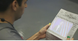
Pranav Mistry Watching A Video On A Newspaper

If you use a projector you can do the exact same thing as displayed in this picture above.

Friday, July 27, 2012

FACE DETECTION USING MATLAB


Image Showing Labelled Faces
Face Detection:


In this tutorial, I present a face recognition system that attempts to recognize faces using the Skin Segmentation Technique. This tutorial is intended to provide an insight into developing a face recognition system using Skin Detection and hopefully gives a good starting point for those who are interested in developing a face recognition system.


There are other methods of face detection in an image, but i structured my own format and it works very well.


My Method:


1. Histogram Equalization
2. Skin Detection and Segmentation
3. Filling The Holes
4. Eliminating Pixels Below a Threshold
5. Putting Bounding Boxes Around Detected Faces And Counting

Step 1:


Brightness Preserving Dynamic Histogram Equalization:


Code:

close all;
clear all;
clc;
rgbInputImage = imread('Your File Here');
%rgbInputImage=getsnapshot(rgbInputImage);
labInputImage = applycform(rgbInputImage,makecform('srgb2lab'));
Lbpdfhe = fcnBPDFHE(labInputImage(:,:,1));
labOutputImage = cat(3,Lbpdfhe,labInputImage(:,:,2),labInputImage(:,:,3));
rgbOutputImage = applycform(labOutputImage,makecform('lab2srgb'));
figure, imshow(rgbInputImage);
figure, imshow(rgbOutputImage);
img=rgbOutputImage;
final_image = zeros(size(img,1), size(img,2));

This routine calls a function fcnBPDHE.(Function Brightness Preserving Dynamic Histogram Equalization.)

You Need To Have The Function saved in your MATLAB directory.


An Image Before Histogram Equalization:


Original Input Image

An Image After Histogram Equalization:


Notice The Increase In Brightness


Step 2:

Detect Skin Regions:

The next step is to detect the skin regions in an image. Photos in which people are fully covered give the best results as the complexity of the code reduces and complex procedures such as neural networks or template matching are not required. But this code does a good job of identifying faces even with some skin shown in the image. 


Code For Skin Detection & Segmentation:

if(size(img, 3) &gt; 1)
for i = 1:size(img,1)
for j = 1:size(img,2)
R = img(i,j,1);
G = img(i,j,2);
B = img(i,j,3);
if(R > 92 && G > 40 && B > 20)
v = [R,G,B];
if((max(v) - min(v)) &gt; 15)
if(abs(R-G) > 15 && R > G && R > B)
%it is a skin
final_image(i,j) = 1;
end
end
end
end
end

Image After Skin Detection And Segmentation:

Some Parts Are Falsely Detected

Wednesday, July 25, 2012

INTERFACING LDR TO 89C51

Light Dependent Resistors (LDR)

SCHEMATIC:


LDR VALUE CHANGES AS THE DISTANCE BETWEEN LAMP AND LDR VARIES

WORKING:

1. LDR GIVES ANALOG SIGNAL AS ITS OUTPUT
2. OUTPUT OF LDR IS FED TO ADC WITH A REFERENCE VOLTAGE
3. THE ADC CONVERTS THE ANALOG VALUE INTO DIGITAL SIGNAL 
4. THIS SIGNAL IS GIVEN TO MICRO CONTROLLER 
5. MICRO CONTROLLER CONVERTS IT INTO READABLE FORMAT AND DISPLAYS ON LCD

ADVANTAGES:

1. CAN BE EASILY INTEGRATED INTO HOME AUTOMATION PROJECTS
2. LESS POWER CONSUMPTION AS CMOS IC IS USED

CODE:

HEX FILE : http://snack.to/czuiy3nx

PROTEUS SIMULATION FILES : http://snack.to/cujsglic

PCB LAYOUT:

AVAILABLE ON DEMAND

COST:

FULL COST: Rs 1000


12V DC TO 230V AC INVERTER

DC TO AC INVERTER 


SCHEMATIC:


12V DC TO 230V AC INVERTER USING 555 TIMER

WORKING:

1. THE TIMER IC EXCITES THE DECADE COUNTER WHICH IN TURN TURNS ON AND OFF THE POWER MOSFETS.( ALTERNATE ACTION )
2. THE TRANSFORMER TRANSFORMS THE SIGNAL WHICH IS GIVEN TO THE AC DEVICE.

COST:

FULL COST: Rs. 500

PCB LAYOUT:

AVAILABLE ON DEMAND


LM35 TEMPERATURE MEASUREMENT


SCHEMATIC:
TEMPERATURE MEASUREMENT USING LM35 AND 89C51

WORKING:

TEMPERATURE SENSOR LM35 OUTPUTS ANALOG DATA WHICH IS CONVERTED INTO DIGITAL SIGNALS BY ADC0804 AND FED TO THE MICROCONTROLLER WHICH PERFORMS COMPUTATIONS AND SENDS THE INFORMATION TO LCD IN REALTIME.

ADVANTAGES:

1. CAN BE INTERFACED WITH SYSTEMS TO ACT UPON SPECIFIC TEMPERATURES
2. CAN BE USED |IN TEMPERATURE REGULATED FANS
3. AIR CONDITIONING SYSTEMS

CODE:

HEX FILE: http://snack.to/czc52ij1

SIMULATION FILE: http://snack.to/cu9abs5k

PCB LAYOUT:

AVAILABLE ON DEMAND

COST:

FULL COST: Rs 1000